This article first appeared in the forum topics of the original knowledge base support site.
Here are some interesting static results from testing six identical uBlox6T units to determine the level of unit-to-unit repeatability achievable under ideal static conditions (strong signals, short baselines). The bottom line: The behavior of the different units is identical for all practical purposes. Under these (again ideal) conditions, each device was able to obtain an RTK fix for over >99% of the time and resolve position to within a <1.2 cm deviation. As is well known, this is an L1 only device and its tracking precision more or less prevents obtaining mm levels of accuracy regardless of the conditions.
Why was this done?
This was done as a pre-mission test before hardening and moving the entire apparatus out in to the field for mobile ground vehicle testing. In that operational environment the fading and recovery of the units as individual SVs tracking is lost is the primary area of investigation. This work was done in support of an the FHWA research grant where SCSC is developing low cost L1 vehicle solutions.
The setup
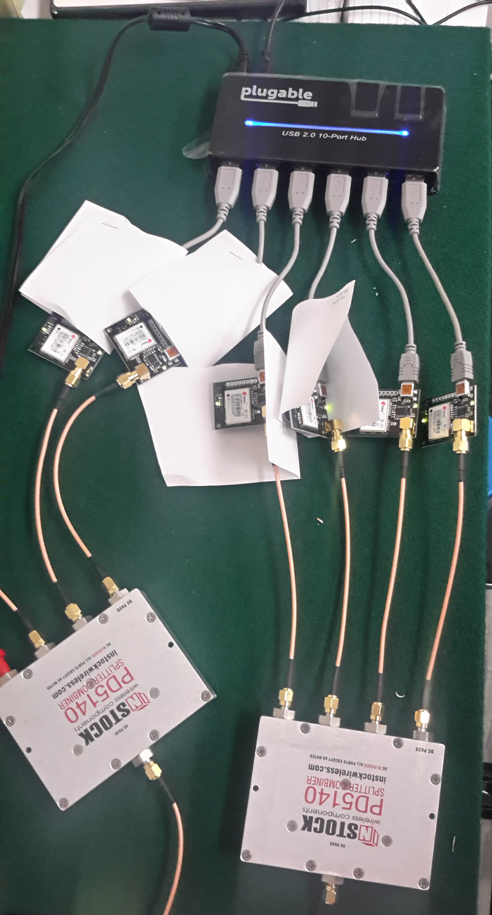 A set of six identical uBlox6T units manufactured by CSG were connected to the same high grade antenna (a Hemisphere A52 unit with 40db of gain) which is used in the firm’s reference station “SCSC2” and data was recorded in 4-hour intervals over 3 days of operation. All units were connected, by means of the USB port, back to a SNIP Caster, which simply recorded the raw observations and logged them. [Aside: While SNIP is marketed as a low cost Caster for small network users, it is also an effective data recording tool for needs like this]
The antenna port of each device was connected to the A52 by means of three splitters in a serial connection. An Instock PD5140 (not shown) 4-way splitter provides the initial connection. This is then fed to an Instock PD5120 and then to an Instock PD5140 and on to each device under test. Signal drop from this path is about 5db, and previous testing with attenuation pads has shown that for the uBlox design this is not a compromising issue (it is for many other devices).
The reference station data used was from “SCSC” whose antenna is located ~130 cm away from the SCSC2 site. Besides the SCSC mountPt, another uBlox6T device (an older EVK-6T-0-001 evaluation unit) is also connected to the SCSC antenna and was compared as a reference device. Data from both of these devices was recorded from the production SNIP Caster at ntrip.itsware.net:2101 in the normal way.
On the right side is a quick and dirty snapshot of the setup in the bench. The small white pieces of folded paper serve to prevent the units from shorting into each other. This of course should be hardened before moving it into a mobile environment. The various cable connection products used are discussed further here.
The post processing
The raw data from each of the devices was recorded by a copy of SNIP operating on a laptop. The settings selected on SNIP created a new file every 4 hours, zipped it, then moved it by FTP to a server. This data was then converted to a set of RINEX files using RTKLIB operating on a windows desktop. The resulting RINEX file set, because it was taken from the ubx messages and not RTCM 1004 messages, included Doppler measurement information. Similar data was obtained for the nearby SCSC reference station (type 1004 messages which contain no Doppler). Daily broadcast orbits were used. After the data collection runs were completed, uBlox6T device number five was found to have collected no suitable data. This was probably due to an error in the setup command sequence sent to it. Therefore none of the results presented use this device.
The RTKLIB v2.4.2 b11 tool “RTKPOST” was then used to process the data set as a “kinematic” RTK filter with an elevation mask of 15 degrees using the “continuous” AR mode with a ratio threshold of three. All other settings were “stock” in nature. The base station position used was determined by a simple first fix, as the absolute accuracy of the position was not of interest.
[Side note: the recently posted bug in RTKLIB where cycle slip counting events are not correctly used to reject an SV after a slip is present in this code. But this is not a material factor. With any well placed reference station antenna such as this one, you only see such slips at the elevation horizon or from passing planes. It will be a considerable factor when mobile testing is done.]
The resulting positional output files were then given further analysis to confirm the lack of anything interesting. Recall that this is a test where success is to see all the units tracking together. Below are a few basic plots taken from one of the four hour periods (14,400 epochs) from each data file. Other four hour periods over the 3 day run have essentially the same results and variances.
The results
[In the below, click on any image to see it at full size]
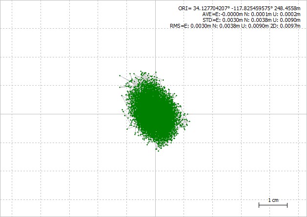
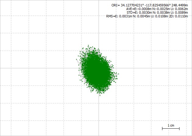 The first set of data is the results of four hours from uBlox6T device #1, plotting only the fixed point. The percentage fixing for all these runs was well over >99%. The general ellipsoidal pattern is the result of the satellite constellation during the 4 hour run.
Recall that these devices are all at the same physical location, observing the data data at the same time. Due to the common shared antenna, there is no multipath element that is unique to each device. These tests serve to give an insight into how “equally” they perform.
The observed 2D deviation was 11.0 mm, and the point to point measurement noise seems to be about half that, i.e. ~5mm. This is all in keeping with typical uBlox6T performance and simply serves to further confirm that our test setup is similar to other uBlox6T evaluations we have performed.
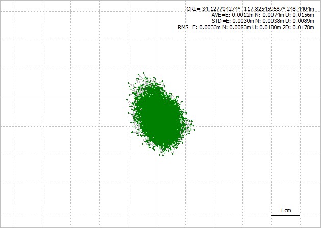
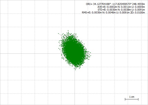
This same analysis process was performed for all the other data sets (devices #2, #3, #4, and 6, device #5 failed to produce suitable data). At right we present the similar graph for device #2, again plotting only the fixed points and noting these were >99% of the observations. The observed 2D deviation was notably larger at 17.8 mm, but otherwise the plot is unremarkable.
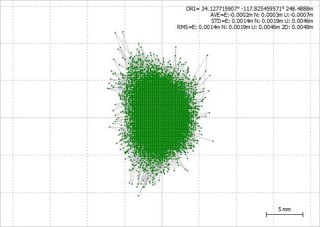
The remaining three devices produced similar plots as well, with slightly smaller deviations, and are shown below.
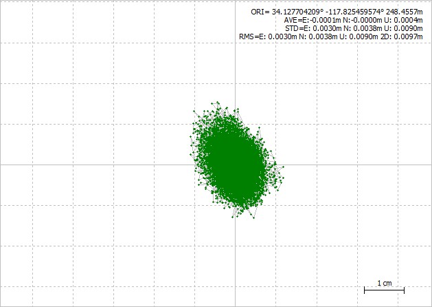
The observed 2D deviation for device #3 was 09.7 mm.
The observed 2D deviation for device #4 was 09.7 mm.
The observed 2D deviation for device #6 was 10.0 mm.
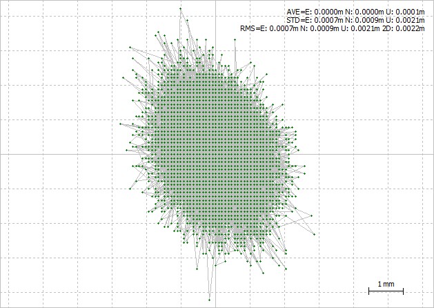
 We also have plotted, using the same navigation settings, a 24 hour data set taken from another uBlox6T device which is connected to the same antenna as the base station being used.
Here, with a zero length base line, we observed a 2D deviation of 4.8 mm. And it should be observed that this type of use will bring out some value decimation and rounding errors present in RTKLIB that would otherwise not be of any concern.
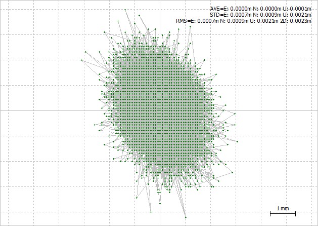
As a final set of plots, it is often useful to compare the difference in values from one device to another at the same measurement epoch. Any visible trends in the sequence of differences or the probability lay out would be of interest. One expects to find filters that lag in some way manifesting themselves. This data appears to fairly white, simply varying about the mean from point to point.
Below are plots of device #1 minus device #2, and device #1 minus device #3. The observed 2D deviation between these devices was 2.2 mm, and 2.3 mm, respectively. This is indicative of the raw measurement noise of the device under these fairly ideal operational conditions. Other comparison plots were similar and are not shown.
Summary
The take away is that the observed 2D deviation was 11.6 mm over the five tested units and appears very repeatably.
As a side effect , this also serves to present data that ~2cm accuracy is obtainable. It also serves to present some data that the raw measurement level of ~5mm is roughly 5x worse than that that found in survey grade devices (at ~100x the hardware cost). These performance value are generally accepted by GNSS developers for this device. But more to the point of the experiment, all five devices performed in same way.
Now that there is evidence that the units track well together under static conditions, the same basic test must be repeated under conditions of rapid signal fading found in the mobile environment. If the units diverge under those conditions it is indicative that the data tracking of each unit is affected by other factors such as correlation loss and recovery times. If the units do not diverge, then the performance data can be used to more effectively model the observed recovery of the device and adapt the navigation filter’s response to it. This is essentially a process of tuning the overall navigation filter to react to signal loss and recovery.
See also summaries of similar ganged testing performed on the uBloxM8T and on the Hemisphere Eclipse P307 in this forum.