The SNIP NTRIP Caster can be used to create corrections streams suitable for use with the SAE J2735 DSRC Message set for delivery to Road Side Units (RSUs) which then broadcast the messages for reception by nearby vehicle On Board Units (OBUs) and use by the vehicle internal GNSS. This allows the vehicle GNSS to use classic code corrections, or RTK methods, or PPP methods, to improve its positional accuracy.
This article describes how to set up SNIP to send these data streams to one or more RSU devices (or any remote IP:Port) using the industry format of UDP sending and encoded in an ASN.1 UPER form.
DSRC = Dedicated Short Range Communication, a short haul 5.9 GHz radio system used for Vehicle to Vehicle communications (now more often called V2X = Vehicle to X (everything)). This is one of several international initiatives to deploy “smart cars” “intelligent transportation” or “self driving” vehicles, etc. Today SNIP is the most widely deployed NTRIP Caster in the world; but was in fact originally created to service this niche market.
Process Flow
SNIP handles the entire translation process providing the following steps:
- Decoding the RTCM messages (all versions of RTCM are supported as well as the private / proprietary message types). The more basic vehicle devices use RTCM2, while more advanced devices use RTCM3. [spacer height=”15px” id=”3″]
- Filtering and performing integrity monitoring on the RTCM content itself. The complete set of PFAT operations are also supported.[spacer height=”15px” id=”3″]
- Packing the desired RTCM messages into the SAE J2735 message format (the ETSI format is also supported).[spacer height=”15px” id=”3″]
- Encoding the resulting DSRC message into ASN.1 UPER format.[spacer height=”15px” id=”3″]
- Further encoding the DSRC message payload into the RSU ‘simple HEX’ format which US RSU devices expect. [spacer height=”15px” id=”3″]
- Sending this payload to multiple RSUs by way of UDP datagrams.
Each destination device has its own dedicated socket and kernel management to ensure low latency and to prevent cross RSU device performance issues. Up to 32 sockets are supported for each DSRC stream. In a typical deployment a common DSRC message payload is created and delivered to sets of regionally co-located RSUs transmitting on Channel 180 (US numbering plan) at a ~1Hz rate.
Within SNIP® this process is handled as another PFAT™ translation, but the control interface is exposed as a Push_Out stream with a few additional control elements to select the set of IP:Port values where the data is to be sent. Once set up, the data simply flows unless there is a detected error which is then reported on the console log to the operator.
Setup Dialog
The DSRC user dialog is based on the Push-Out dialog. But in addition to sending the data to another Caster (in this case the data is sent back to the local SNIP Caster) some DSRC specific information can also be entered. A typical empty dialog is shown below.
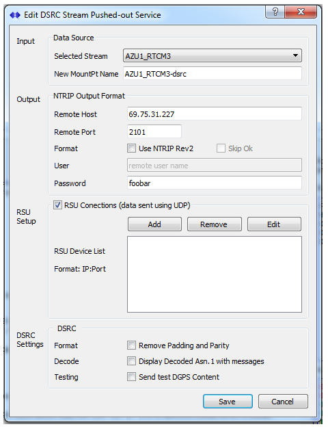
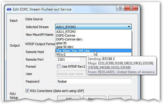
The operator first selects which Base Station data stream will be used. SNIP provides the normal tool-tip information to further describe the content and general location of the streams.
Note: Once you select which data stream is to be used from the drop-down, the ‘traditional’ Push-Out setup details are populated for you including appending the word “-dsrc” to the mountPt name, adding the IP and port of your local machine, and adding the default local access password. You do not need to enter these values by hand.
[Aside: This is an example of the SNIP Caster folding a data stream back into itself for further processing (called loopback). A similar use can be found when a given data stream needs to be sent out in more than one Reference Datum using PFAT to Transform the ECEF antenna location.]
The operator then enters the sets of IP:Port address which the final data will be sent to (described next). These are typically RSU devices servicing a region of roadway covered by the selected Base Station.
The check box labeled RSU Connections (data sent to UDP) represents the master on/off switch for sending out the UDP data. To disable sending, you can either un-check this box or disable the stream itself at Push_Out tab level.
Four additional check boxes are used to control the content which is sent out, and the level of console logging shown. Note that the first two of these only have effect when sending RTCM2 messages, they are ignored for RTCM3 and other content types.
- The check box labeled Remove Padding and Parity can be checked when a strict adherence to the message content encoding rules of SAE J2735 is needed. This will remove the ‘6of8’ bit to byte encoding and the running parity bits (resulting in an even parity for all messages). Using this results in a 40% message payload size reduction. But then required the DSRC decoder at the other end (typical an OBU device) must replace the parity before sending the result to the GNSS device. We recommend you do not check this box unless your end user community is very familiar with RTCM 2.x message decoding details. [spacer height=”20px” id=”2″]
- The check box labeled Pad RTCM2 messages with <cr><lf> allow adding a final 2-char pad to each RTCM2 type message when checked. This has been added to support some receiver devices that cannot otherwise detect RTCM2 message framing. We recommend you do not check this box unless your end user community requires this. [spacer height=”20px” id=”2″]
- The check box labeled Display Decoded ASN.1 with messages controls the display of ASN.1 structure details in the console and is discussed further in a moment. [spacer height=”20px” id=”2″]
- The check box labeled Send test DGPS Content will (when checked) replace the live RTCM message with a predefined static message for test uses. [spacer height=”15px” id=”3″]
Selecting the IP:Port for UDP sending
The key difference between a traditional Push_Out stream and an DRSC Push_Out stream is that when servicing DSRC streams, a set of UDP sockets is opened to send datagrams with a common message to each defined endpoint. Up to 32 endpoints can be specified per stream (at least one is required in order to send data). Up to three different DSRC streams can be created. This could result in as many as 96 additional sockets being opened.
[By contrast, in the normal SNIP Push_Out mode, the Caster assumes the role of an NTRIP Server, sending to the remote NTRIP Caster, by way of a single TCP/IP connection where packet delivery is acknowledged.]
In order to complete the DRSC setup process, at least one IP and Port is required to send the data to. This port will get the DSRC payload bytes expressed in a ‘hex string’ in the RSU format. Press Add… to enter a new IP:Port value.
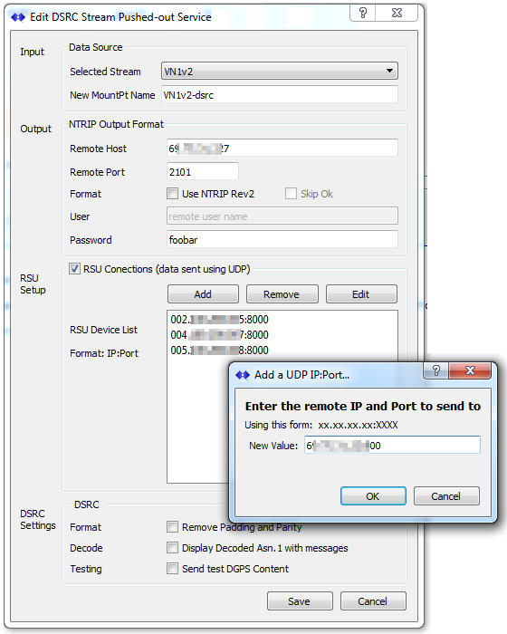
Support for adding IP:Port pairs involves three buttons (Add, Remove, and Edit) and the simple dialog box shown above. Enter data for each destination in the format indicated with a “.” between IP octets and “:” before the port number. Textual URL values are not allowed. Entering incorrect data is ignored (and noted in the console). Entering more than 32 IP:port pairs is not allowed.
Upon pressing Save the stream settings are saved out and the stream is started after ~15 seconds (if the selected source data is present and ready). The stream can be Connected and Disconnected using the normal right-click menu in the tab. Right click and select Edit to return to this dialog when changes need to be made.
Stream Tool Tips
The informative per stream tool-tips used in the tables shows some additional information when a DSRC stream is displayed. The list of the RSU IP:ports that the data is being sent to is shown, as well as a data summary of the message counts and data sent.
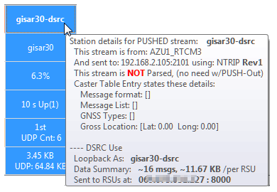
As is typical for a PUSH_Out stream, the data itself is not parsed (having been parsed and processed on the input side). The DSRC unique content is shown at the bottom. The message count shows the DSRC messages sent (not the RTCM message count which would typically be higher). The data sent shows the size of the accumulated DSRC messages sent. Both values are for a single RSU (not the sun of all RSUs). Because UDP transport is used (rather than TCP/IP) SNIP is not able to determine how many datagrams were successfully received by the remote devices. [The DSRC ‘message count’ data element value, a modulo 128 counter, can be used for this.]
Message Decoding
In any SNIP data stream the operator can right-click in each stream and select the menu item Show Message Types to be shown additional content details about the messages in that stream. This is generally used to confirm that the stream message contents are as expected. When the stream content is DRSC, some additional details are also provided as described below.
The list of IP:Post destinations is shown. If any socket is backing up or reporting connection errors, this is also displayed here. If any port is sending data back to SNIP (which would be an incorrect protocol use), this is also shown. Any such content is read and discarded. In the below example a 642 byte payload is being sent to three streams (the IP values are not obscured in the actual display).
[gisar30↑]:   MountPt gisar30 has sent 95 Bytes [#R001]. A summary decoding may follow.
[gisar30↑]:       Detected the potential presence of RTCM rev3.x msg content, (enable PARSE to see details).
[gisar30↑]:       RTCM3 messages Found: MTs: 1004, 1008, 1012, 1230 (11) (11 in all)
[gisar30↑]:   Sending RTCM 3x content consisting of: MT1004 (139 bytes), MT1012 (095 bytes), Msg Content Size: 234 bytes
[gisar30↑]:   [DSRC translate->] Datagram sent to IP:69.xx.xx.227 on Port:8000, wrote 642 bytes (4,209th DSRC msg, 2.981 MB sent)
[gisar30↑]:   [DSRC translate->] Datagram sent to IP:79.xx.xx.108 on Port:8010, wrote 642 bytes (4,209th DSRC msg, 2.981 MB sent)
[gisar30↑]:   [DSRC translate->] Datagram sent to IP:3.xx.xx.6 on Port:1234, wrote 642 bytes (4,209th DSRC msg, 2.981 MB sent)
In addition if the checkbox labeled Display Decoded ASN.1 with messages has been set in the above dialog, a human readable decode of the ASN.1 encoded DSRC message is also displayed when Show Message Types is enabled. [Aside; like any stream, the raw content can also be logged to a file for post processing.]
[gisar30↑]:   Sending RTCM 3x content consisting of: MT1004 (155 bytes), MT1012 (112 bytes), Msg Content Size: 267 bytes
[asn]:   Decoded DSRC MessageFrame contents are:
MessageFrame {
   messageId = 28
   value {
      RTCMcorrections {
         msgCnt = 113
         rev = rtcmRev3
         msgs[0] =
d3 00 95 3e c0 00 77 31 9c 62 90 79 22 55 70 04  ...>..w1.b.y"Up.
6c 3f d2 6e 30 48 c0 ba a7 fc 4b 83 cf e2 40 04  l?.n0H....K...@.
2a 96 97 35 81 18 00 b5 72 d3 c8 24 3a c6 00 8f  *..5....r..$:...
07 f4 8b dc 11 a0 1f e3 ff 0c 73 43 19 ac 03 fe  ..........sC....
3f a5 57 e0 79 80 a9 57 f7 52 45 da db 3f db f9  ?.W.y..W.RE..?..
fd 16 f7 04 af fa a8 3f cf 08 36 d8 9b fc 64 bf  .......?..6...d.
e9 b4 58 22 bf 70 9d fd 6d b2 46 a2 28 0c a9 ff  ..X".p..m.F.(...
4d 9c c1 49 02 15 cf f1 03 b2 b4 93 c0 08 53 fa  M..I..........S.
2d d6 05 48 02 ac 7f 92 15 48 cf b9 ff db 5a 54  ‑..H.....H....ZT
69 b0 39 bf f3 b7 4b f0 9d 12 73                 i.9...K...s
         msgs[1] =
d3 00 6a 3f 40 00 96 24 09 03 02 65 36 82 c4 bf  ..j?@..$...e6...
fc c5 8a 68 b4 09 9f ff 68 63 16 39 9a 45 72 af  ...h....hc.9.Er.
ff 3a fe 83 11 02 bf ff 31 7f db 94 06 68 75 d0  .:......1....hu.
01 09 3f a1 bd 20 00 80 00 00 00 04 1a 4e 69 4d  ..?.. .......NiM
00 1e af e8 b1 10 17 00 12 7b fd b0 c1 8d 76 15  .........{....v.
7e 6e cb fa 68 62 00 08 00 00 00 00 48 a9 00 e5  ~n..hb......H...
8f fc 49 fe 8b 05 02 3b fe a9 ff d9 00 01 13 c7  ..I....;........
      }
   }
}
This display has value as a debugging aid for the RSU and OBU developer. It also allows an easy visual method to see how SNIP has packed one or more RTCM messages into the single DSRC message. In the above example above two common RTCM3 messages, MT1004 (legacy GPS observations) and MT1012 (legacy GLO observations), have been combined into a single J2735 DSRC ‘RTCM’ message (which is assigned the message ID 28).
Note: The ability to send J2735 encoded ASN.1 message content is an advanced feature. It requires a Pro license and depends on the presence of an active “SAE J2735” Plug-In to be used.