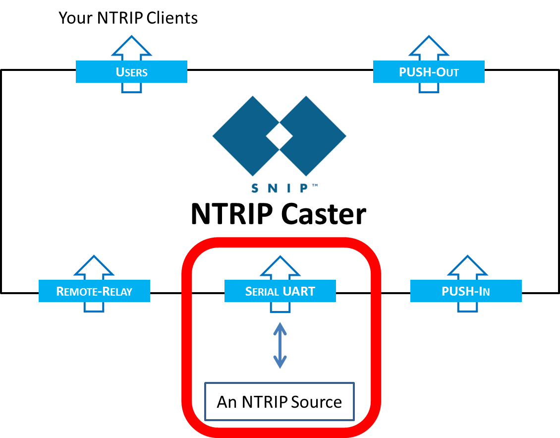
 SNIP allows adding data from one or more serial ports as data streams to the Caster. Here is how to set up a serial port connected to your GNSS device. This eliminates the need for the NTRIP Server element as SNIP becomes both the NTRIP Caster and and performs the NTRIP Server function in this case. The Lite version of SNIP allows up to three such connections, while other levels allow more slots for more simultaneous connections.
There are three general steps to adding a new device to a serial slot.
- Serial Port Configuration Establishing the comm port, baud rate, etc.
- Serial Commands Sending any setup commands to the device, an optional step.
- Edit the Caster Entry Enter the mountPt data, so the caster can advertise it to others.
Each of these are quickly covered below, with additional detailed information about each dialog presented in other articles in the knowledge base. Once any setup data about a port has been entered, it is retained and will be used when SNIP next powers up. Hint: If you have enabled the Auto Start check-box, then all your serial streams will be automatically restarted without further intervention.
For the purposes of this example we will connect to a UART port of a common uBlox 6T type device, using a DB9-pin to USB adapter. [We could have connected to its native USB port as well] In this simple example setup, SNIP will serve the device’s proprietary data stream out under the mountPt name “uBlox6T”
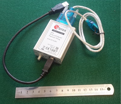
Aside: A common alternative with this type of inexpensive device is to use a tool like RTKLIB and its StrSvr (Stream Server) tool to convert from the proprietary message formats of the device to RTCM3 messages, and then feed the resulting data stream to SNIP, either by serial port or having StrSvr act as an NTRIP Caster. This is a popular way to create a very low cost L1-only reference station suitable for many short baseline uses. Here is an article to set that up on SNIP using PUSH-In streams. This connection method has the added advantage that the RTKLIB can be remote from the SNIP machine location.
Getting Started
Start with an empty (unused) serial slot you will see in the image below. Right click on the slot (or the Add New Stream button) and you will see four commands which are unique to serial stream data, as well as the same common menu controls used in other streams. You can also see (in the right boxed label) that no caster table information (the mountPt and other details) has yet been set up for the serial stream slot.
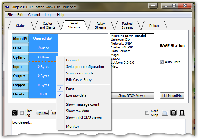 Hint: If you already have created a serial setup in a slot, simply edit it to reflect the new data settings and SNIP will copy over it.
Serial Port Configuration…
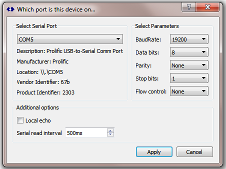
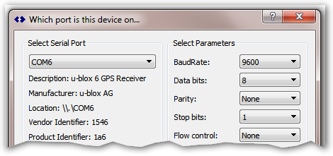
The serial port dialog allows setting the UART port parameters in the normal way. For many devices, only the Baud rate needs to be set. If you do not see any ports to select from, be sure the device was plugged in BEFORE launching the dialog and that there are suitable working device drivers installed for your operating system. In general, if any other tool can connect to the device, so can SNIP. Be sure to select a baud rate that will support the data you wish to send.
Here we have used the dialog and selected com5 in a Windows device (port 5), where a Prolific USB to serial device is located. We have used a Baud rate of 19.2 kbps, which experience has taught us works well on this device.
 Had we elected to connect to the native USB port of the uBlox device, the description and the manufacturer text would differ, (as well as the port used) displaying the text below. This raises an important point that the driver text displayed reflects the driver, which may or may not be the name of the GNSS maker. Often it is the name of an intermediary firm which provided the driver software to the GNSS device or to the serial-USB cable / converter.
For additional Information on using the serial connection wizard for this, click here. Also, this article has some practical advice on serial and USB adapters you may need to obtain.
Serial Commands…
If you have already set up your device to output the correct message types needed, you can skip this step.
Often tools provided by the vendor are the best to establish the correct setup commands On many GNSS devices these can be saved into device memory for further use between connections and/or power cycles. Other devices require this information to be provided with every power cycle, so SNIP provides a means to send sequences of such commands to the device to put it into a known state at both setup and shutdown times.
For a uBlox device the free tool uCenter provides this control functionality. It is common to connect to uCenter with the USB port for general control while sending selected raw data to another device (such as SNIP, RTKLIB, etc.) on the provided 9 pin serial port (UART0).
The basic operation of the serial command dialog is to select an existing file that has the commands to be sent. Once selected, the file can be edited and saved within the dialog window to facilitate small changes. Checking the Show Send check-box causes a verbose log of each command (and its reply) to be shown to assist in debugging. Otherwise, only a summary of the commands and replies is shown. A basic set of command files for several popular devices is provided with SNIP. In the absence of a selected valid file, no commands are sent.
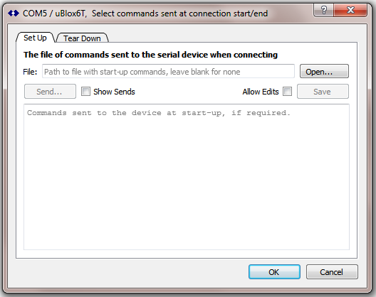
Current Status: At this time command files are only supported for uBlox device models 6T and M8T and for Hemisphere Eclipse models. The Hemisphere method support a common “one line of text” command style used by most of the world’s other vendors. Other devices can be added as requested.
For additional Information, click here.
Edit the Caster Table Entry…
Every Data Stream has its own Entry in the Caster table. This table allows each user to see what the Caster offers and select the best data stream for their needs.
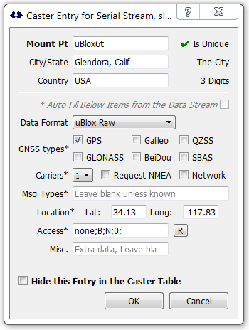
The new data stream must have a locally unique Mount Pt name to differentiate it from other streams. It is also customary to provide additional informative data about the stream such as its gross location, GNSS types, its data contents, and a few details regarding how to connect to it. This information, formatted with one line per data stream, makes up one of the the Caster Table entries. This table is sent to clients on request, or when the clients attempt to mount a caster that is not valid. Many NTRIP Clients also can use this data to provide visual maps of the caster holdings to the user in the field similar to what SNIP does on the desktop.
It is not essential that all this information be present; only the Mount Pt is required. The Mount Pt must be a single word and must not contain certain characters. The Mount Pt “uBlox6T” was used in the below example. And it is best to remember that case matters. The tool will check the entry for you to ensure that it is unique and will provide various corrective hints for the different data entries when needed. It will prevent duplicate mountPt strings, creating an alias if required. If you enter (under user preferences) your home town and location, this information will be filled in each time for you for any new ports.
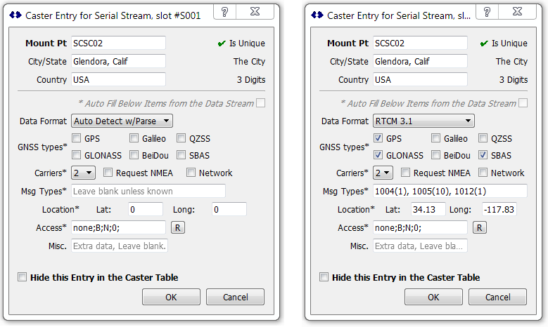
If your data consists of common RTCM-3 messages, then as best practice, the data format “Auto Detect /wParse” is to be preferred. No other details then need to be set, SNIP will do the rest.
In this mode, SNIP will perform an initial analysis your data steam when it first starts and then correctly fill in the Caster Table entry for you, including the types and rates of the messages, the gross location of the Base Station, the GNSS types (GPS,GLO,etc.), signal types (L1/L2/L5), and the other details.
Here are two typical images of a high grade Base Station with a serial port setup. The one shown on the right has every data item set by hand, similar to the uBlox example above. The one on the left uses SNIP‘s ability to do stream analysis on RTCM 3.x messages to produce the same resulting caster table entry.
You can also elect to “hide” this data stream from being added to the published Caster Table entries by checking the indicated box. This feature (which is not available on the Lite model of SNIP) has some value when you do not wish other parties to see the full set of data streams which your copy of SNIP supports.
Running the Serial Stream
Because in this example we are NOT using any RTCM-3 messages (rather we are using uBlox raw data), we also need to uncheck the “Parse” command. This control setting instructs SNIP to simply rebroadcast whatever the data source provides.
In general, processing the RTCM-3 messages provides other advantages such as monitoring and plotting the message flow. We also will log the data file for record keeping. Note: The default setting with all new streams is to parse the data and to log it. Any changes which you make to these settings are recorded and kept in the INI file for the next use. [Changes which cause the display of messages, raw data, various chart plotting, or decoded RTCM3 data are discarded on restart to keep the the display less cluttered.]
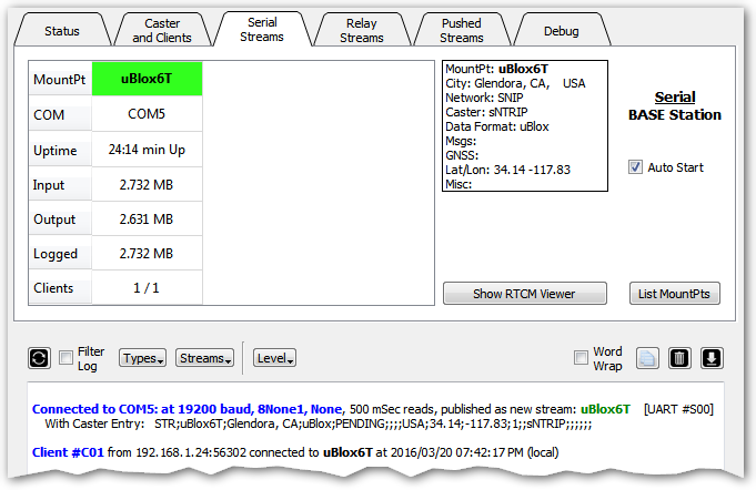
Ready to start? Right click the “Connect” menu comment and the process will begin. You will see a summary of the connection details, mountPt and the console log. In the example below, an incoming client connection was made to this stream a few moments later. If a sequence of setup commands was sent, a summary of that would also be shown.
After a few minutes of operation your Serial Streams tab will look similar to this. The example below shows that the uBLox6T mount point (in serial slot index #S00) has 1 current active client connection (of 1 in total over its lifetime), and has served out 2.631 MBytes of data over >24 minutes, while logging about 100k more (the log started first, then the single client connected about ~100k after that).
The details of the caster table entry are shown in the label on the right. And, because Auto Start is checked, this port will be restarted when SNIP is restarted to allow unattended operation. The white area to the right of the slot summary is where any additional serial streams would be displayed. The green color, following the pattern of the other tabs, indicates a current state of error free operation.
That’s it! Your GNSS device is now connected to a fully functional Caster which can serve the serial devices’ data stream to the users you allow to connect. See this article for how to add and control your subscribers (user accounts).
Update: SNIP now has a serial port wizard that will lead you over the same steps.
Problems with your setup?
To understand and connect all the physical cables, this article covers the hardware side.
To understand issues with device drivers, see the article: Problems with USB / Serial Drivers