Probably not the one you have now if you are asking this question.
We presume in this FAQ that you have obtained a low cost L1 device,
and that you wish to do RTK navigation to obtain ~2cm accuracy over moderate to short baselines.
If you received a small magnetic puck antenna as part of your GNSS device, replace it with something suitable. While it is possible to use this antenna in some static conditions, it is rather unlikely you will be able to do any mobile work with it. And if BOTH your rover and and your reference station are using this sort of antenna, you are more or less doubling problems you can easily avoid.
The golden rule regarding how to invest your money in GNSS technology is not unlike that famous rule for real estate: Location, Location, Location! The first and very best thing you can do to ensure success is to select a suitable open sky location for your reference antenna site. The next is to select a suitable antenna. This is in fact more important than the GNSS system you select, because any corrupting influences introduced in the antenna propagate into the GNSS observation and become very hard to then remove. [Finally of course a good L1/L2 GNSS device is wanted, although for baselines under 10~15km there are many applications that can achieve solid centimeter performance with inexpensive L1 only products such as the popular uBlox.]
Why does an inexpensive puck antenna not suit? Because the phase delay and phase center of the antenna will vary as much as ~60 cm depending on the angle and elevation at which the GNSS signal comes into it. And this will also vary significantly depending on the effective ground plane where you place it. Do not even think about placing such an antenna “on the dash” for the rover side in a vehicle, or “on the ground” when standing nearby or over it, or “at your desk” indoors – even if you are in a wooden home. All of these examples will be so corrupted by multipath as to be unusable. A clear view of the sky is essential for success in the base station. In this discussion, integrated antenna solutions and hybrid antenna with other signals in the same physical design (such as GNSS and cellular) are typically also a poor choice for achieving high accuracy.
By contrast, the phase bias found in a “good” antenna has a variation of less than two centimeters (geodetic grade devices are in the range of fractions of a mm, see also Footnote A). Recall that the carrier wave of the L1 signal is 19 centimeters, and that to achieve a “fixed” state (ambiguity resolution, or AR) requires that the precise number of these wavelengths must be determined and tracked for each GNSS signal. Once locked on, the carrier is being tracked to a resolution of tens of picoseconds, pretty impressive for a signal that is 12,000 miles away! In other words, if your choice of antenna is adding an unknown changing value of three wavelengths of measurement bias based on the angle of arrival for each signal, that is making it rather hard for your navigation filter to achieve a fixed AR solution. And then, when the vehicle rotates and changes heading, it all shifts yet again. The key message here is: If you want to use an L1 system under such conditions, please invest in a suitable antenna.
So, back to which one?
In the absence of weight restrictions for your mission (such as a drone application), we recommend selecting your antenna from one of the many proven avionics antenna designs available for L1/L2 GPS/GLONASS use. They are designed to be all-weather devices, fairly small, and of fairly moderate price. Chose one with L2 support if at all possible. From a strict theory point of view, the optimal antenna to meet a given requirement set does not admit other signals which are not required (matched filter theory), but selecting an antenna that supports L2 or GLONASS, even when they are not required for your day-one mission needs, is often a wise investment.
The antennas you will want to consider are all “active” in that they require a DC power voltage (supplied by your GNSS device over the coax) and they have a gain value you need to match to the expectation of the GNSS device to be used, minus the signal loss due to the the connectors and coax. Typical gain ranges are 10~40 db, and this may also vary depending on the coax length and connectors you select as well. Keep all coax lengths as short as practical to avoid signal loss.
Aside: If your reference GNSS maker has a suitable antenna they recommend, we suggest you use that. In fact many GNSS manufacturers will not guarantee that their device will meet stated performance levels unless their antenna is also used. Expect to pay $1k~$4k more (US dollars) for such antennas.
We hesitate to recommend one design over another, but here is a unit we have been using for urban automotive testing as well as for reference stations for over half a decade with great success. Using this antenna model we routinely hold <2cm levels in moving vehicle equipment. The maker, Antcom is a well established provider of GNSS antennas; their catalogs have many solutions serving a variety of RTK and other needs. And unlike some others, the design of this unit has been calibrated. The unit below, in L1/L2 form, is about $450 US in single quantities.
The model that we often use is: Antcom 53GO1216A4-XT-1 antenna.
This is an L1/L2 GPS/GLONASS design suitable for all but the highest accuracy needs. In the above part#: The 4 indicates 40dB gain. The T indicates a TNC connector (use “S” if you prefer the smaller SMA). X means no cable pigtail is present.
Our own local representative / dealer contact is:
Rex Williams,
GeoNAV
387 Maryville Avenue
Ventura, California 93003-3930 U.S.A.
Phone: 805-650-6525
Fax: 805-650-6588
rex@geonavsystems.com
 Click for further details on these items
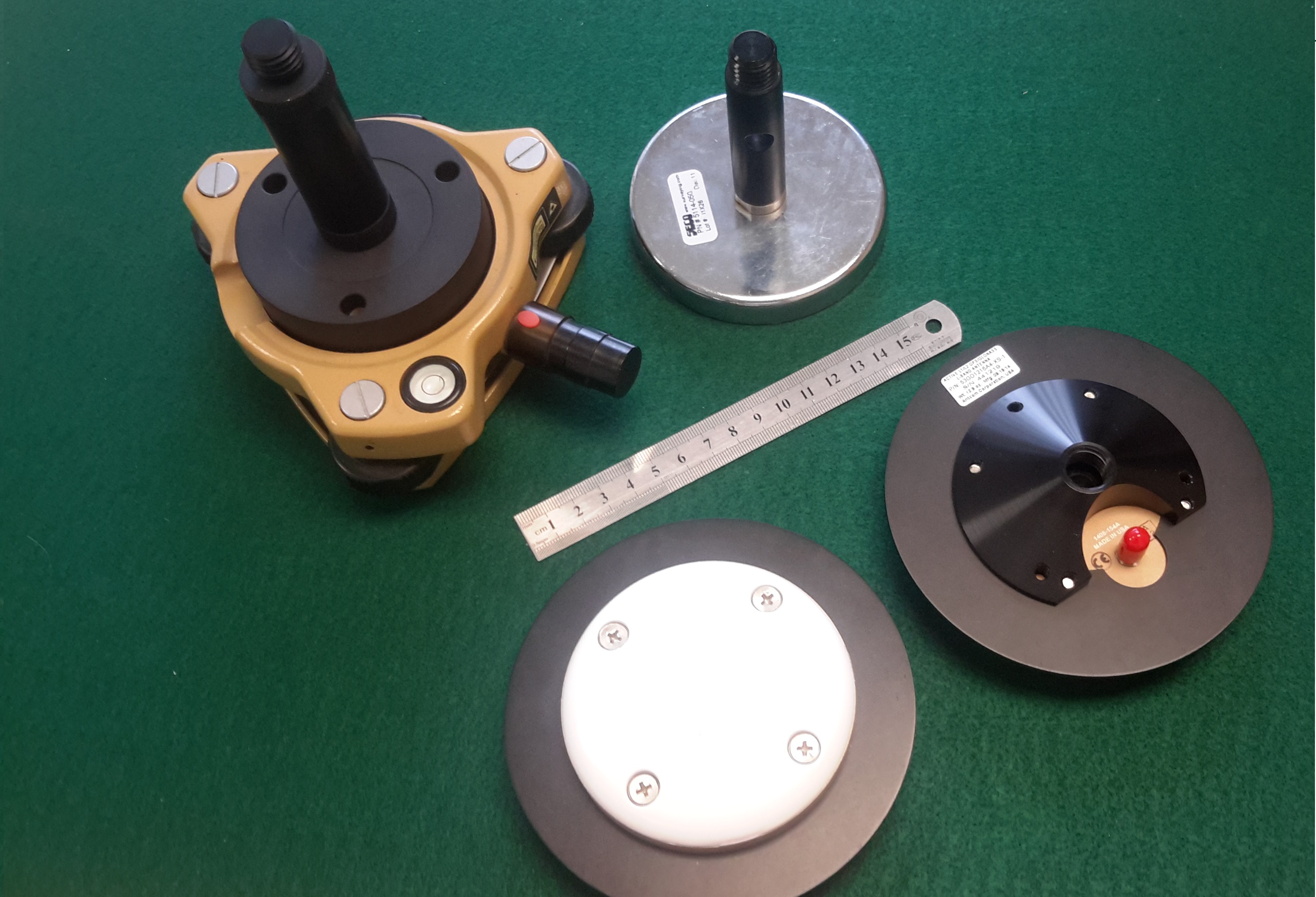
You will note that this unit, as do many others, comes with a 5/8 inch (and 11 TPI) threaded connector (you will see this size called “19mm” in some catalogs). The 5/8 size and threads are an international standard for survey equipment use. Most tripods accept this type of mounting, as do the magnetic mounts shown in the above picture. If you will be using this on an automobile roof, the 3-inch extension post is essential in order to allow the SMA coax connector access to the bottom. We typically leave the small metal ground plane attached when testing.
Footnote A:
For high grade units and applications, a table of offsets for the antenna bias variations in phase delay over azimuth and elevation has been developed by independent testing processes (supported by various sources of government funding). These tables can be obtained for many devices at this point (including the Antcom unit recommended above). If you cannot find the model you want to use in these tables, it may be either new or just not suitable. The reference station software then uses these bias values to subtract/add to the raw carrier phase observations before sending them out in the RTCM3 messages to achieve the highest possible accuracy. As part of this process, the reference station antenna is installed with a known orientation (there is typically a mark that is pointed to the North). All that the operator needs to do is load in the antenna model that is being used. This process is typically not performed in the rover as the orientation angle changes with movement, but it is common to orientate the rover antenna forward.
For uBlox Developers:
Here is a very good application note that servers as a practical guide for antenna section and placement issues published by uBlox that relates mostly to rover antenna usage. Keep in mind this information was developed for a code-only tracking type of system, which has much less precise needs than the needs of a carrier tracking system (i.e. RTK).