This article covers the basics of how to setup a uBlox chip set to utilize RTCM2.x style corrections.
In general the SNIP knowledge base articles do not provide Vendor or Model/Device specific setup instructions, preferring to point to documentation directly from the maker. But as uBlox is often used in conjunction with RTKLIB tools and the commercial products based based on that; we make an exception and group this article with others relating to the use of RTKLIB.
[Aside: Beside the web sites maintained by each product developer, UNVACO offers very good setup instructions for survey grade GNSS devices. See: https://kb.unavco.org/kb/category/gnss-and-related-equipment and enter your equipment type into the search field. This is the best place on the web for detailed setup instructions for your Base Station]
This article consists of both detailed instructions regarding how to set up a uBlox chip using u-Center to import and use RTCM2, and a variety of historical ‘asides’ with data on RTCM, NMEA, and GNSS in general that may be of interest to the reader.
Background
Many of the various low cost L1-only uBlox chips, including the 6T and 8 series (as well as the latest F9P) can be used for traditional RTK navigation and positioning. These chips provide an output of the raw code and carrier tracking data (the “observables”) which can then be used by a external navigation filter such as the popular RTKLIB tools. It requires only modest effort to develop and deploy robust and accurate RTK and/or SSR solutions in embedded products using these resources and a nearby Base Station. Many of the users of the Lite model of the SNIP NTRIP Caster do precisely that. The newest uBlox offering (the F9P chip) now provides L2 tracking as well as multiple constellations and a built-in RTK navigation filter. A data stream from a nearby Base Station is still required (providing RTCM3 or SSR content, or both), but this serves to continue the industry trend of RTK becoming a low-cost commonplace commodity.
However, there remains a number of users and use cases who wish to use RTCM2 “code” corrections rather than RTK or SSR style solutions. [Aside: Besides the RTCM2 message types 1,2,3,9, and 31, RTCM2 also provides a very early form of RTK which is no long recommended for use and is not considered further here.]
The reasons for using RTCM 2.x vary, but often such users simply wish to hold sub-meter accuracy in a moving ground platform. The availability of SBAS/WASS corrections is often further compromised in ground vehicles due to urban blockages, particularity at higher latitudes where geostationary transmissions are often blocked. The ~15 minute acquisition of the full ionospheric map is also problematic for real time vehicle applications. The largest remaining user segment for RTCM 2.x is found in coastal marine applications (harbor approach, etc.). Aside: During times of low solar activity, RTCM2 is frankly not that much better than SBAS, but during periods of higher actively, both RTCM2 and RTCM3 perform markedly better.
For these users, RTCM 2.x represents a marginal accuracy improvement over SBAS, but nothing like the 100x improvement achieved with RTK.
Equipment Used: In this article we have used an older uBlox 6T device with firmware 7.03 in the examples. Eight years ago we demonstrated using these devices with modified copies of RTKLIB to perform rapid cold start RTK Fix acquisition in a moving vehicle. The primary modifications to RTKLIB involved adaptive weighting of the Kalman filter based on the instantaneous SNR and Doppler values to detect and reject transitory multipath. In turn that work led to the creation of the SNIP NTRIP Caster. Most of the screen shots shown below are taken from u-Center (revision 20.10), the software provided by uBlox to set up and monitor their chips.
Overview
By default, the uBlox chip defaults to using SBAS/WASS corrections signals when these are present. It must be expressly told to use RTCM2. Some GNSS devices will automatically move between RTK, DGPS/DGNSS, SBAS, and true autonomous modes depending on the available data they are given. This is not true for uBlox. [See caution about NMEA-183 $GGA sentence below as well] Aside: In this document we will treat the term “DGPS” (differential GPS) and “DGNSS” (differential GNSS) as being equivalent.
Beside being told to use RTCM2, various ports must be enabled and configured to receive the data (see next section). And the corrections data needs to contain ‘code’ DGPS messages (message types 1,2,3,9, and 31).
Aside: For a list of the defined RTCM2 messages see this article.
It appears that uBlox is tolerant of other RTCM 2.x message types being present in the data stream (such as the retired RTK messages expressed in messages 18,19,20,21), correctly reading them in and then ignoring them. This has not been verified with all chip sets. Aside: This behavior is according to the RTCM 2.x specification and is generally true for other GNSS devices as well.
It appears that uBlox is tolerant or decodes the improved antenna messages in RTCM 2.x, types (22,23). But it is not known if it makes any use of them. For code corrections use, this information is of almost no additional value.
It appears that uBlox is tolerant of the presence of additional <cr><lf> characters being present in the data stream. Again, this has not been verified with all chip sets. Aside: RTCM2 was originally developed for transmission over a serial communications link using a big-endian ordering. When converted to octets the 30 bit parity words are expressed in 5 octets. When then sent over TCP/IP or a serial cable, some Base Stations will add additional <cr><lf> characters between each message frame. This is not in fact defined or allowed by the current RTCM standard, but is commonly seen. A well designed receiver device should be able to cope with either style.
When DGPS data is present, the uBlox chip immediately decodes it and moves from “autonomous” to the “DGPS” mode of operation (the value of ‘1’ to the value of ‘2’ in NMEA). Note that this may take ~3 seconds depending on how often the data stream is sending the messages of interest. When the data is removed, the uBlox chip remains in the DPGS mode for 60 seconds. You will see that ‘age of DNSS’ indication in the $GGA sentence increasing during such times. After 60 seconds have elapsed without any new data, the uBlox chip reverts to the “autonomous” mode of operation. [The timeout value can be set with UBX ⇒ CFG (Config) ⇒ NAV5 (Navigation 5) at the bottom of the dialog] This can be verified with both u-Center and the NMEA $GGA or $GLL output sentences (see below). See How do you know it is working below for a quick recap of key indications.
Terminology Asides: The term “autonomous” indicates operation without external corrections, it is also called “single” in some GNSS tools. In the uCenter tool it is called “2D/3D” and this is also where uBlox provides a fixed altitude operating mode. Some GNSS devices describe their mode as autonomous when they are in fact using SBAS/WASS corrections information. Other devices will describe the same operating mode as “DGPS” (differential GPS/GNSS) so the reader is advised to check. The NMEA-183 specification is very vague on this point, that part of the standard having been written before the deployment of SBAS/WASS corrections. Further the term “DGPS” is generally held to refer to the use of code corrections only (which are then directly subtracted from the observed code measurements by the rover device, hence the name). By contrast the terms “RTK” or “NRTK” (network RTK) are used to refer to RTCM 3.x messages with code and carrier phase measurements where the rover device code and carrier measurements (the observations) are combined with the measurements from the Base Station in a “double difference” navigation filter. To complicate this still further; the RTCM message set standard which defines all the RTK messages is still formally uses the term “Differential” in it’s title.
Process Steps
We presume in these instructions that a working copy of u-Center is connected to the device in question and that the serial port “UART1” is connected and available for use (to send the DGPS data stream in with). We would recommend a baud rate of 19.2k or higher to ensure that no data is dropped.
Aside: The tool u-Center is now 15+ years old and the product of many different user demands (uBlox states that 100+ people have contributed to it). It is not particularly intuitive, with related functions spanning different dialog boxes and settings. The GUI uses a common interface for all the uBlox chips, even if a specific chip does not support a given feature. The primary GUI feedback to indicate that a given feature is not supported is a grayed out control. However, this also is used to indicate that the feature is simply disabled. The only way to tell one from the other is a detailed review of the specification sheet for the device you are using. The firmware revision is also very important, as some features are present only in later revisions.
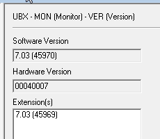
To see the firmware revision use the dialog in uCenter found at: UBX ⇒ MON (Monitor) ⇒ VER (Version) and press poll for the data.
Step #1 – Disable SBAS use.
Go to the dialog at UBX ⇒ CFG (Config) ⇒ SBAS (SBAS Settings). Select disabled in the combo box. Send this message to the device (the send button is along the lower left side of the dialog). Your dialog should look like the below:
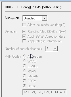
The device will now accept and use RTCM2 code corrections data when it is found to be present. But we must still set some other controls to ensure the data is processed, and then we must provide the data.
Aside: The u-Center GUI uses a combination of dialog styles; some of which can send data to the device such as this one, others which can only display data. Many dialogs also allow a periodic polling mode of use where the displayed data is automatically updated. Use the polling mode to watch data such as the DGPS corrections data change and evolve over time.
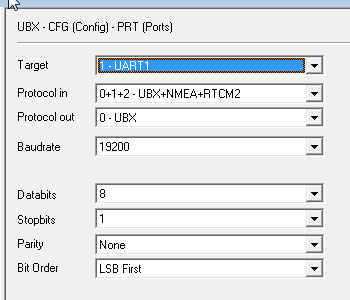
Step #2 – Enable Uart1 for RTCM2 input
Go to the dialog at UBX ⇒ CFG (Config) ⇒ PRT (Ports). In the combo box, select “1- UART1” – this brings up the setting controls for this port. Besides the obvious baud rate and serial details (we recommend 19.2k or better), there are two combo boxes that control the supported “protocol” in and out. It appears that the design of the uBlox chip employs a sort of “directed pipe” style where (in this case) you must tell it at which port a given protocol will appear. There is also some (conflicting) evidence (not explored further here) that the RTCM2 input can only be present on one port at a time.
Set the values as shown below, the critical detail is that RTCM2 be an input (Protocol in) on UART1 . Other values can also be made to work. In particular, you may want to send NMEA sentences back out to assist in data logging. Send this message to the device.
Step #3 – Connect a suitable data Stream
Now would be the time to send RTCM2 correction to UART1 (matching the same baudrate etc., you set above). See the next section if the process of doing this needs further explanation.
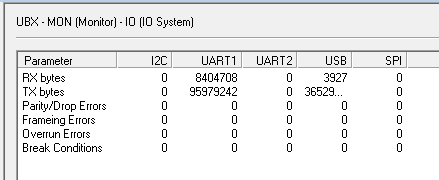
When data is being received on UART1, you can use the dialog found at: UBX ⇒ MON (Monitor) ⇒ IO (IO System) to observe data (measured in octets) arriving at the different ports (in this case the Rx bytes field for UART1).
Aside: The dialog found at UBX ⇒ MON (Monitor) ⇒ RXBUF(RX Buffer) can be used to check the receiver buffer sizes. A similar buffer (TXBUF) exists for the transmit side. These are of value to detect and correct buffer overruns if the baud rate is set too low.
Note that IO (IO System) dialog now shows a count of all bytes transferred. Ensure that data is being received from your DGPS source.
This dialog shows data is being received. It does not indicate that the bytes are meaningful. In other words; that they are correctly formed RTCM2 message content. We will use another dialog for that.
Go to the dialog at UBX ⇒ MON (Monitor) ⇒ MSGPP (Message Parse and Process). This dialog shows the uBlox device’s ability to decode and classify the message content it sees on each port (Step #2 told it to expect RTCM2 content on this port). As shown below, you should see a (growing) count of RTCM2 message content on UART1. This dialog shows that the data received has been decoded as valid RTCM2 content. It does not indicate that the RTCM2 message content is the correct type(s) to be used for DGPS. Once again, we use another dialog for that.
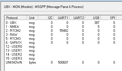
Aside: Keep in mind that anything the device does not understated will be classified as “UNKNOWN” So as an example, if you were to send valid RTCM3 content to most uBlox chips (except the F9P), it would appear as UNKNOWN because it is not decoded.
Go to the dialog at UBX ⇒ NAV (Navigation) ⇒ DGPS (DGPS Data). This dialog shows the actual decoded DGPS information. The data age will vary between ~0.5 and ~3 seconds. The PRC and RRC values for each reported satellite will updated as new messages arrive. The PRC (pseudo range correction) is the value that is used to adjust what the uBox chip has measured. The RRC (range rate connection) is a 1st order model used to propagate the correction value forward in time.
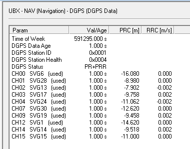
The above does indicate that theRTCM2 message content in the correct type(s) is input, parsed, and be used for DGPS in the uBlox device. If you see this data, the uBlox chip is being correctly feed. We can now examine the navigation output and the NMEA outputs in greater detail to learn how the corrections have changed (improved) the positional output (next step).
Aside: The above was done with a uBlox 6T device and it does not appear to decode RTCM2 message type 31 (code corrections for GLO satellites). It is not clear what message types newer designs will decode. Current adopted RTCM2 supports GPS+GLO, but there are some deployment with code corrections for other GNSS constellations using message type 59.
Step #4 – Observe the Navigation details
There are two easy ways to determine if the uBlox chip is using the RTCM2 message content. One can look at the uCenter “NAV” solution dialogs, or one can look at the NMEA-183 messages being output. The second method is of particular value when uCenter is not connected to the device.
In the uCenter navigation status dialogs
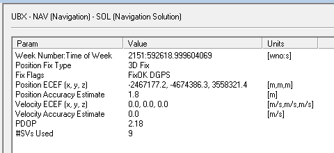
Go to the dialog at UBX ⇒ NAV (Navigation) ⇒ SOL (Navigation Solution). This dialog shows general information about the current postilion estimate.
Note the field marked “Fix Flags” and the value “DGPS” indicating that RTCM2 corrections are being employed.
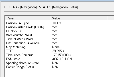
Go to the dialog at UBX ⇒ NAV (Navigation) ⇒ STATUS (Navigation Status). This dialog shows similar information about the general status of the navigation filter.
Note the field marked “DGNSS Fix” and the value “Yes” indicating that RTCM2 corrections are being employed. The field “Diff Corrections Available” is also of note.
In the NMEA-183 messages
This information can also be visually decoded in the $GGA and $GLL sentences. Here we again use the uCenter tool to decode the message for us.
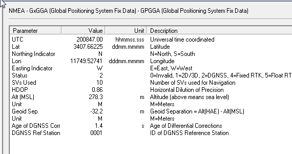
Go to the dialog at NMEA ⇒ GxGGA (Global Positioning Systems Fix Data) ⇒ GPGGA.
In the $GGA sentence, the data element “Status” will be “2” if DGPS is being actively used (see below). A value of 0 indicates no positional fix (GPS not working or no position is determined). A value of 1 indicates an autonomous mode of operation (no corrections present).
Aside: The values 3 and 4 refer to float and fixed RTK modes (when the wavelength ambiguity is not resolved the device is said to be in a float mode). Other values are not universally agreed upon and different device manufactures use different values for the same operating modes. This is a point of great confusion. Further, some device manufactures will decode and use SBAS/WASS corrections and report in the NMEA sentences they are using a differential mode (i.e. 2), while other will report this as an autonomous mode (i.e. 1).
Note that value for “Age of DGNSS Corrections” (here shown as 1.4 seconds). This value changes as the latency in the messages evolves. It is generally less than a few seconds. If it exceeds 60 seconds, the device will drop back to an autonomous mode (see prior comments regarding how to set this threshold).
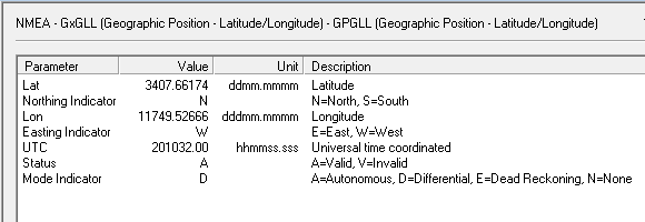
In a somewhat similar way the $GLL sentence can be used.
Go to the dialog at NMEA ⇒ GxGLL (Geographic Position – Lat/Lon) ⇒ GPGLL.
Here the key inform is found in the “Mode Indicator” field where D=Differential operation.
Note that “Status” has a different meaning that that used in the $GGA sentence.
Key Take away:
Any of these methods is sufficient to determine if
the uBlox device is using the DGSS corrections.
Connecting to SNIP for data streams
In order to send corrections data to the uBlox chip obtained from any NTRIP Caster (such as SNIP) an NTRIP Client is used. Here we have used a popular PC based tool from Lance Lefebure, download it here: http://lefebure.com/software/ntripclient/ It is suggested this be download and run from the same PC that u-Center is run from. A common USB to serial cable can then be used to send the data stream to the uBlox device over its uart1 port.
It appears that the current version of the u-Center tool now has both and NTRIP Client and an NTRIP Server built into the tool. Presumably these could be used to acquire corrections and send them to the uBlox device under test. We often see others doing this on the RTK2go node, but have not investigated the setup process further here.
Connect the Lefebure NTRIP client to a Caster in the normal way, selecting an RTCM stream that contains nearby (<100km baseline or better) data to the device under test. Here we have used a Base Station provided by ESRI which is located 50km away from the uBlox device.
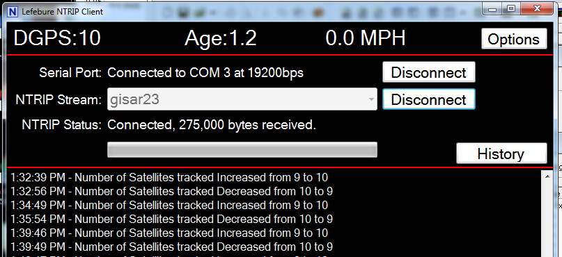
The Lefebure tool, when connected and running, also displays the location in periodic NMEA sentences when available.
Note also you can have SNIP record the NMEA data from the connected clients in various ways for post processing. See the AVL tab for further details.
How do you know it is working
In this uBlox device a $GGA sentence with the mode set to 2 (indicating DGPS) confirms that the corrections have been used.
To recap the key check points from the above:
- See if data is being input with
UBX ⇒ MON (Monitor) ⇒ IO (IO System)[spacer height=”15px” id=”3″] - See if data is being parsed with
UBX ⇒ MON (Monitor) ⇒ MSGPP (Message Parse and Process)[spacer height=”15px” id=”3″] - See if data is being used with
UBX ⇒ NAV (Navigation) ⇒ DGPS (DGPS Data)[spacer height=”15px” id=”3″] - See the DGPS in use indication with…
- In the Navigation dialog with DGNSS Fix or the “Fix Flags” showing DGPS present.
- In the NMEA $GGA sentences look for the mode flag = “2” which indicates that DGPS is in use.
Other related links for uBlox
Here are some other articles using uBox devices which may be of interest
An example with L1-only uBlox devices with 1km baseline testing
Multiple 6T device testing results
What Antenna should I use, general advice for inexperienced users
Connecting USB Serial ports to your PC
What is inside a uBlox evaluation module (6T units)